|
Hull Construction |
|

Click on image to enlarge
Roger's Notes:
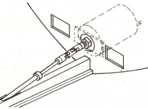
Although you are using an universal joint, you still must align
it as close as possible.
  
Slip the output
shaft of the motor through the hole in F2. Slip the universal
over the output shaft of the motor and over the prop shaft, as
shown. Do not tighten the screws on the universal.

Press the motor mount against F2 and
align the output shaft with the prop shaft, as shown. Then, mark
the location of the motor mount on F2 with pencil marks.
Roger's Notes:
If necessary, the hole in F2 can be enlarged to provide adequate
clearance for motor alignment.


Carefully apply
Slow CA to the motor mount. Reattach the motor on the
universal. Align the motor mount with the pencil marks and press
it against F2. Hold it in position until the Slow CA cures
(about 20 seconds).
Roger's Notes:
Re-check the
alignment of the prop and motor shafts before the Slow CA cures.

Remove the motor
and universal. They will not be needed again until construction
is completed.
Alternate Motor Installation
Roger's Notes:
I
installed my motor after I completed through Step #150. I
finished planking the hull and applying the fiberglass. If
you choose to use this same powering system, I suggest you also
complete assembly steps through Step #150 and then return to the
Alternate Motor Installation.
First thing
I did was to obtain the needed Dumas motor and Master Airscrew
3.5:1 gearbox.

Click on image to enlarge
After I opened the motor and gearbox, I assembled the
universal joint.
Roger's Notes:
I don't remember IF I drilled out one
Coupling Socket
to
fit the Master Airscrew 3.5:1 gearbox or I used a
coupling socket for a 3/16" drive shaft
that I already had. Sorry... but they are
easy to buy.
After I assembled the
universal joint I aligned it
over the plan with the
prop, prop shaft and stuffing box.
Roger's Notes:
You will not have to do this step because I know this system
will work with very little modification needed.

Click on image to enlarge

Click on image to enlarge

Click on image to enlarge
|
|
Antenna & Steering Tubes
 
Check the position of the steering tube, relative to the
steering arm, by inserting the braided cable into the steering
tube. The cable should come out of the back end of the steering
tube and pass close over the inside hole on the steering arm, as
shown. Also, the cable should slide easily in the tube. If
necessary, adjust the steering tube in the frames to obtain the
correct fit. Then, use Slow CA to glue the steering tube to the
frames and steering tube support.

Remove
the braided cable, steering arm, rudder shaft and rudder post.
Place these parts back in the Hardware Bag.
Motor Installation
There are many different
ways to install electric motors in model boats. The method shown
in your manual and described here applies to the Midwest MEPS-III.
It is available from your hobby dealer.
Roger's Notes:
The instruction manual for this model tells you to install the
Midwest MEPS-II Marine Motor and the MEPS-II Speed Control Unit.
Midwest NO LONGER makes the MEPS-II MEPS-II Marine Motor and the
MEPS-II Speed Control Unit. They now make the
MEPS-III
Motorizing System (Stock #836).
This includes a
system which
includes everything you need to run your boat.

If
you decide to use a different motor and installation method, as
I did, Midwest suggests that you read through this sub-assembly
anyway. It will illustrates how to align the motor with the
universal and prop shaft.
If
you will be using the MEPS-III Marine Motor, you will need a MEPS-III,
Stock #836 (or an equivalent electric motor, motor mount and
universal) to complete this sub-assembly.
Roger's Notes:
I tried a new powering system on this model that I have not yet tried
before. The
system I used and will describe used an
Dumas
6 Volt Motor 18-33" Boats
and a
Master Airscrew 3.5:1 Gearbox
that was suggested to power the ORCA model. This is
detailed at the end of the Motor Installation section.
The Dumas motor includes the following items:
One 540 size motor
Two 6-32 X 1/4" hex screws (hex ball driver size=1/16")
Two brass drive dogs
(diameter=3/8", length=1/2")
Four 6-32 X 1/2" slothead screws One nylon dog bone
(diameter=3/16", length=1 1/4")
Two motor plates (length=2 3/8", width=1")
MEPS-III Marine Motor Installation
Assemble
the motor on the motor mount, as per the instructions for the
MEPS-II.


Assemble
the universal, with the idler, as shown.

|