Fitting the Running Gear
  
Now after all the work you put into your
hull, we have to make some holes in it. ;-) Two are needed for the stuffing boxes,
and two for the rudder tubes.
You must first determine if you are happy
with the support struts if you purchased them from BaD. I was not happy with mine
and decided to modify them to look more scale. This decision is yours.
Locate the exact center of your hull as a
reference, then draw a line down the center stern area. Now, locate the distance
where the main support is located and draw a line 90ş to your reference line. This
line will now be your reference line to determine the elevation of your shafts. Using
your center referance line, mark your referance line for your propeller shafts.
This information is provided on the plans.
(Click on thumbnail
to view larger picture)
Roger's Notes: I used
the plans that I got from the Floating Dry-dock
for the placement of my props, shafts and supports. I had to modify the measurements
a bit to compensate for the differences in the BaD hull. For this reason, I will not
give exact measurements. :-(
I made a jig out of plywood to support the
shafts at the right height. The hull was marked where the ends of the shafts rested.
I enlarged the holes to accept the stuffing boxes.

(Click on thumbnail
to view larger picture)
Roger's Notes: I did
NOT use the stuffing boxes supplied with the kit. I made my own.
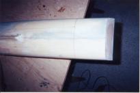
Lightly sand your stuffing
boxes and fit them into the hull. Now slide the shafts into the stuffing boxes and
support the end of the shafts at the transom with the jig. Leave the shafts and jig
in place. I used tape to secure the shafts in alignment. Now add epoxy around the
stuffing boxes. I used 5 min. for this step. Then, mix some more epoxy and
micro balloons. Add this around the outside of the hull where the stuffing boxes
exit. Trim, and sand to contour when dry.
|
|
(Click on thumbnail
to view larger picture)
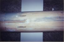
After the epoxy has dried on the outside, add
epoxy around the stuffing boxes on the inside of the hull. Don't skimp on the epoxy
in this step. You want to make sure there are no holes and the joint is water tight.
I tend to add a pool of epoxy in my boats to add support to the stuffing box and
surrounding balsa (hull).

Locate the items you will need to make your support
struts. I used streamlined brass tubing for the struts and used the hubs supplied
with the kit. With the shafts inserted into the stuffing boxes, support the other
end with the jig. Use your source (my source was the plans from the Floating
Drydock, yours may be the instruction manual), and locate reference lines for your support
legs. Then take an measurement from each reference line to the shaft. Make
sure to subtract the thickness of your hub. This will give you the length of each
leg. The legs on each support have different length for the inboard and outboard
legs! The kit support legs were the same size.
I used a home made jig to solder some tabs on
the hubs to accept my suppots. The system you use is up to you. I also had to
mill a slot to accept my tab in the smaller hubs. BaD ships these with only one
support leg.

(Click on thumbnail
to view larger picture)

(Click on thumbnail
to view larger picture)
Roger's Notes: Awe, now
it's starting to look like I'm getting something done. As for the props, they have 5
flat blades set at about 45ş. I don't plan to replace them, they are tolerable.
Enough said.
 |


