|
Finishing Details |
|


The door outline shown on the plan
is made by cutting black striping tape into thin strips and
sticking it to F2.

Roger's Notes:
The door outline can
also be made by masking off F2 and painting the outline. I
did my door outline using an easier technique. The
pictures and text below will explain how I did my model.
First, I made a template of
the door from scrap wood. I used the outline of the
door from the plans. I positioned the template on F2 as
shown on the plans. Then I used a sharp #2 pencil to make
a light tracing of the door on F2.

Click on image to enlarge

Click on image to enlarge
Roger's Notes:
Please note that in the picture above, I made my door tracing
before I added the dashboard trim. Using a template and
pencil can still be used if you have installed the dashboard
trim. Just account for the trim when you make your
template from the plans.

Use Walther's
Goo to glue the brass door hinges over the door outlines, as
shown. Drill a 1/8" hole just inside the door outline to
simulate a finger hole for the door latch.

|
|
Cockpit
You will need the parts illustrated in your manual to complete
this sub-assembly. The die-cut part is in Bag Number Three (#3).
The basswood strip is in Bag Number Two (#2). The remaining
parts are in the Accessory Bag.
You
will also need the previously built and painted cockpit roof,
and about 12" of black striping tape.

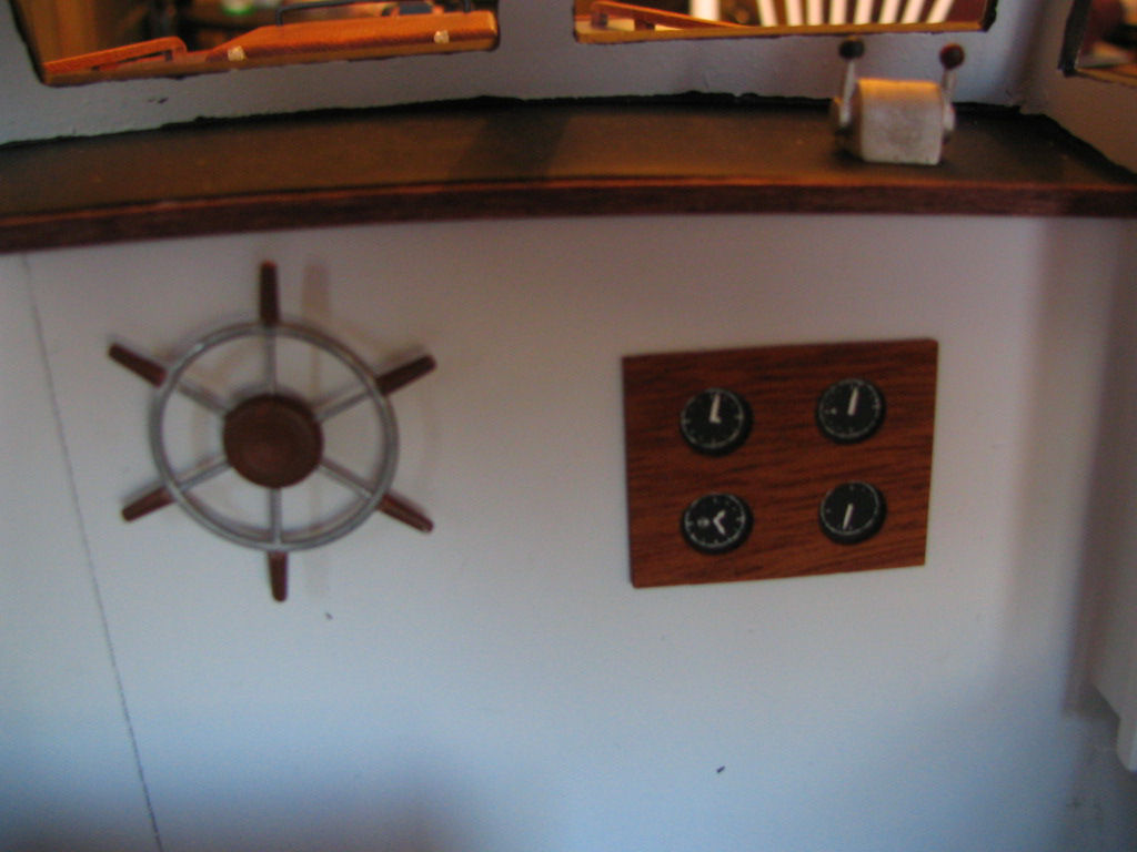
Remove the wood from the holes
in the mahogany instrument panel. After finishing the instrument
panel with clear urethane, use Slow CA to glue the instruments
to the back of the panel so the instrument faces show through
the holes. Then, use Slow CA to bond the instrument panel to F2,
in the position shown on the plan.

Click on image to enlarge


Click on image to enlarge

Click on image to enlarge

Drill a 1/16"
hole through F2, at the location shown on the plan for the
wheel. After painting the wheel and engine control box, use Slow
CA to glue them in the positions shown here and on the plan.


|